Archive for the ‘networking’ Category
OpenVPN-AS와 Google Authenticator/ Authy 연동 설정하기
알고보니, OpenVPN-AS의 경우 Google Authenticator/ Authy 연동을 쉽게 할 수 있었다.
Authentication 메뉴에
– General
– PAM
– RADIUS
– LDAP
가 있길래, RADIUS 혹은 PAM으로 할까 했는데,
의외로 메뉴가 숨어 있었다.
Configuration > Client Settings 메뉴로부터
설정 가능하다.
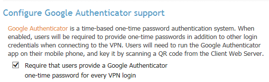
과 같은 체크박스가 있고, 체크해 주면 된다.
그리고, VPN 서버에 반영 혹은 재시작 시키자.
이것만으로는 접속시 OTP를 사용할 수 없다.
(아직 OTP 등록도 하지 않았으니까)
기존에 OTP 설정 전에 받아 놓은 opvn 프로파일을 사용하여 VPN 접속을 시도하면,
OTP를 묻지도 않고, 기존 방식과 동일하게 인증하고 접속시켜 버린다.
OTP 설정을 위해, 처음의 절차를 다시 밟자.
클라이언트로부터 https://주소:943을 접속해보면, 이전과는 다른 화면을 볼 수 있다.
ovpn 프로파일을 받는 부분 하단으로, google authenticator 안내문과
QR코드 그리고 직접 입력할 경우를 대비한 코드가 보일 것이다.
이 정보를 활용하여, QR코드로 찍든 코드를 직접 입력하든 선택하자.
이 단계에서 google authenticator를 사용하거나, authy를 사용하거나 상관없다.
내 경우는 authy를 사용해서 테스트 했고, 정상적으로 등록 가능했다.
그리고, 다시 OVPN 파일을 클라이언트로에 다운로드 하자.
OTP 설정 이전의 프로파일은 클라이언트로부터 삭제하자.
새로 받은 프로파일을 사용하여 VPN 접속을 시도하면,
이제 기존의 id/password와 함께 OTP도 함께 묻는 것을 확인할 수 있다.
아이폰으로 집의 네트워크에 VPN으로 접속하려면?
나중에 다시 할 수도 있는 재설치를 위해 기록으로 남겨둔다.
예전에 사용하던 IPTIME 공유기를 가지고 있었다면,
일단 우선적으로 공유기에서 제공하는 VPN 기능을 검토했을 것이다. (그랬으면 쉬웠을텐데..다시 살까?)
일단, 현재 집에서 사용하는 공유기는 Netgear 공유기이다.
이 모델에는 VPN 기능이 제공되지 않는다.
따라서, 검색/ 정보 수집을 통해 PPTPD, OpenVPN, OpenSwan 등을 조사했으며,
공유기 내부에서도 잘 동작한다고 알려진 OpenVPN을 설치하기로 하였다.
우선, OpenVPN에 대한 설치파일/세부 정보는 openvpn.net으로부터 확인할 수 있다.
최초 설치 시도는 CentOS VM상에 yum install을 통해 설치/실행하는 것을 진행하였으나,
OpenVPN-AS(Access Server)가 설치가 쉽다는 내용을 접하고, OpenVPN-AS로 급선회하였다.
OpenVPN Server와 달리, AS의 경우 설치 과정이 매우 간단했다.
해당 RPM 설치 후, 모든 설정을 관리자웹 상에서 설정해 주기만 하면 될 뿐만 아니라,
사이트내에 각 기능별 설명들이 기본적으로 표기가 되어 있어서 도움이 되었다.
(OpenVPN 서버의 경우, 기본 값들이 무슨 기능을 하는지 주석이 달려있기는 하지만,
다소 설명이 부족하다는 느낌을 받았다.)
1. 집 네트워크 구성
PC1 -+
|
PC2 -+—-+ 공유기 +—-+ ISP 공유기 +—-+ 인터넷 +—-+ 아이폰
|
PC3 -+
예전에 케이블 인터넷을 사용했을 경우, ISP 공유기 대신 케이블 모뎀이 위치했고,
내 공유기 설정에서 포트포워딩을 설정해주는 것만으로 집 내부 PC들에
접근이 가능했으나, 이사 후 ISP 제공 공유기가 앞단에 더 존재하게 되어 ISP 공유기
설정도 함께 변경해 줘야만 내부 접근이 가능하게 되었다. (DMZ로 설정하거나, 다른 룰을 추가하거나)
2. VPN 연결 개요
위의 환경 구성을 바탕으로, VPN을 다음과 같이 환경을 구성하였다.
+——————————- VPN Tunnel ——————————–+
Linux –+
(VPNGW) |
NIC#1(e) |
NIC#2 |
|
PC1 –+—-+ 공유기 +—-+ ISP 공유기 +—-+ 인터넷 +—-+ 아이폰
NIC#3 | NIC#5(e) NIC#7(e) NIC#9
| NIC#6 NIC#8
PC2 –+
NIC#4
* e : external
집 내부 공유기 내부에서의 PC들간은 별도의 설정이 없어도 공유기에 연결한 것만으로
NIC#6를 통해 NIC#2, NIC#3, NIC#4끼리 통신할 것이다.
내부에서 외부로 접속하고자 한다면, NIC#5를 거쳐 나갈 것이다.
다만, 위의 경우와 같이 2개의 공유기를 거쳐야 한다면, NIC#5로부터 #8, #7을 거쳐 외부로
나갈 것이다.
Linux를 VPNGW로 삼고, 외부에서 이 Linux를 VPNGW로 접속하여 PC1,2로 연결하도록 하는
것이 목표이다.
3. OpenVPN-AS 설치
http://www.openvpn.net에 접속하여, OpenVPN-AS(Access Server)를 다운로드한다.
내 경우는 CentOS용 RPM을 다운로드하였고, 설치하였다.
passwd openvpn
을 실행하여, openvpn 계정의 비밀번호를 변경한다.
그러면, 추후 OpenVPN관리자 계정의 비밀번호로 사용할 수 있게 된다.
설치는 일반 OpenVPN 서버 설치 과정에 비해 OpenVPN-AS 설치 과정이 훨씬 간단했다.
(easy-rsa를 사용한 server, client 인증서 생성 등의 과정을 별도로 할 필요가 없다.)
정상적으로 설치가 되었다면, https://vpngw의 비공인 IP:943으로 접속하면,
OpenVPN-AS의 관리 페이지가 뜬다. 이 때, 인증서를 신뢰할 수 없다고 뜨면 무시하기를
눌러서 진행하자.
1) 서버용관리 – https://주소:943/admin
2) 클라이언트 – https://주소:943
서버용 페이지에 접속하여 살펴보면, 좌측의 큰 메뉴 기준으로 Status/Configuration/
User Management/Authentication/Tools 메뉴가 존재한다.
이 메뉴들 중, 실제로 내용 수정을 한 페이지 기준으로 기록한다.
* Status : 별도 수정 항목 없음
* Configuration
– License : 기본 라이센스 (2명)
– Server Network Settings
– Hostname or IP Address : 내 집에서 달고 나가는 공인 IP (공유기 관리웹에서 확인하거나, 내 IP를 확인해 주는 사이트 등을 통해 확인 가능)
– Interface and IP Address : NIC#2의 주소 기록
– VPN Mode : Layer 3 (routing/NAT)
– VPN Settings
– Dynamic IP Address Network : Network Address 디폴트값 그대로 사용 (ex – 172.27.224.0)
– Routing : using NAT
– Specify private subnet : NIC#2, #3, #4용 (ex – 192.168.1.0/24)
나머지 값들은 기본 값을 그대로 사용해도 된다.
이렇게 서버를 설정하고 나서, 클라이언트의 원활한 설정을 위해 집 내부망에서 아이폰으로
https://주소:943으로 접속해보자.
그러면, 클라이언트를 다운로드할 수 있는 링크가 출력되고, 아이폰의 경우 결국 AppStore에서
OpenVPN 클라이언트를 다운로드할 수 있도록 연결된다.
클라이언트에서 접속한 웹 페이지로부터 하단의 링크를 클릭하면,
직접 profile을 다운로드 할 수 있다. 다운로드한 파일을 OpenVPN 클라이언트에서 열기를
지정해주면, 결국 이 설정 파일은 OpenVPN 클라이언트에 import 되면서, 자동으로
프로파일이 추가된다.
(만약, OpenVPN-AS버전이 아니라 Community Edition으로 직접 수동 설치를 진행했다면,
인증서 파일 및 클라이언트 설정파일을 복사/수정하여 client.ovpn 파일을 만들어 주었어야
했을 것이며, opvn 파일 및 인증서 등을 itunes를 사용하여 동기화 해주거나, 이메일로
직접 전송해서 import시켜야 했을 것이다.)
이후, 아이폰의 네트워크를 3G/LTE 등 외부망으로 선택하고, OpenVPN 클라이언트를 통해
접속시도하면, 성공적으로 VPN 접속이 이뤄지는 것을 확인할 수 있다.
IP를 확인해보면, 터널IP를 새로 받은 것을 확인할 수 있으며, telnet 클라이언트를
이용하여 내부망에 있는 PC로 ping을 날려도 정상적으로 동작하는 것을 확인할 수 있다.
[RFC 2338] VRRP (Virtual Router Redundancy Protocol)
Network Working Group S. Knight
Request for Comments: 2338 D. Weaver
Category: Standards Track Ascend Communications, Inc.
D. Whipple
Microsoft, Inc.
R. Hinden
D. Mitzel
P. Hunt
Nokia
P. Higginson
M. Shand
Digital Equipment Corp.
A. Lindem
IBM Corporation
April 1998Virtual Router Redundancy Protocol
Status of this Memo
This document specifies an Internet standards track protocol for the
Internet community, and requests discussion and suggestions for
improvements. Please refer to the current edition of the “Internet
Official Protocol Standards” (STD 1) for the standardization state
and status of this protocol. Distribution of this memo is unlimited.Copyright Notice
Copyright (C) The Internet Society (1998). All Rights Reserved.
Abstract
This memo defines the Virtual Router Redundancy Protocol (VRRP).
VRRP specifies an election protocol that dynamically assigns
responsibility for a virtual router to one of the VRRP routers on a
LAN. The VRRP router controlling the IP address(es) associated with
a virtual router is called the Master, and forwards packets sent to
these IP addresses. The election process provides dynamic fail over
in the forwarding responsibility should the Master become
unavailable. This allows any of the virtual router IP addresses on
the LAN to be used as the default first hop router by end-hosts. The
advantage gained from using VRRP is a higher availability default
path without requiring configuration of dynamic routing or router
discovery protocols on every end-host.Knight, et. al. Standards Track [Page 1]
RFC 2338 VRRP April 1998
Table of Contents
1. Introduction………………………………………..2
2. Required Features……………………………………5
3. VRRP Overview……………………………………….6
4. Sample Configurations………………………………..8
5. Protocol……………………………………………9
5.1 VRRP Packet Format………………………………10
5.2 IP Field Descriptions……………………………10
5.3 VRRP Field Descriptions………………………….11
6. Protocol State Machine………………………………13
6.1 Parameters……………………………………..13
6.2 Timers…………………………………………15
6.3 State Transition Diagram…………………………15
6.4 State Descriptions………………………………15
7. Sending and Receiving VRRP Packets……………………18
7.1 Receiving VRRP Packets…………………………..18
7.2 Transmitting Packets…………………………….19
7.3 Virtual MAC Address……………………………..19
8. Operational Issues………………………………….20
8.1 ICMP Redirects………………………………….20
8.2 Host ARP Requests……………………………….20
8.3 Proxy ARP………………………………………20
9. Operation over FDDI and Token Ring……………………21
9.1 Operation over FDDI……………………………..21
9.2 Operation over Token Ring………………………..21
10. Security Considerations……………………………..23
10.1 No Authentication………………………………23
10.2 Simple Text Password……………………………23
10.3 IP Authentication Header………………………..24
11. Acknowledgments…………………………………….24
12. References…………………………………………24
13. Authors’ Addresses………………………………….25
14. Full Copyright Statement…………………………….271. Introduction
There are a number of methods that an end-host can use to determine
its first hop router towards a particular IP destination. These
include running (or snooping) a dynamic routing protocol such as
Routing Information Protocol [RIP] or OSPF version 2 [OSPF], running
an ICMP router discovery client [DISC] or using a statically
configured default route.Running a dynamic routing protocol on every end-host may be
infeasible for a number of reasons, including administrative
overhead, processing overhead, security issues, or lack of a protocol
implementation for some platforms. Neighbor or router discoveryKnight, et. al. Standards Track [Page 2]
RFC 2338 VRRP April 1998
protocols may require active participation by all hosts on a network,
leading to large timer values to reduce protocol overhead in the face
of large numbers of hosts. This can result in a significant delay in
the detection of a lost (i.e., dead) neighbor, which may introduce
unacceptably long “black hole” periods.The use of a statically configured default route is quite popular; it
minimizes configuration and processing overhead on the end-host and
is supported by virtually every IP implementation. This mode of
operation is likely to persist as dynamic host configuration
protocols [DHCP] are deployed, which typically provide configuration
for an end-host IP address and default gateway. However, this
creates a single point of failure. Loss of the default router
results in a catastrophic event, isolating all end-hosts that are
unable to detect any alternate path that may be available.The Virtual Router Redundancy Protocol (VRRP) is designed to
eliminate the single point of failure inherent in the static default
routed environment. VRRP specifies an election protocol that
dynamically assigns responsibility for a virtual router to one of the
VRRP routers on a LAN. The VRRP router controlling the IP
address(es) associated with a virtual router is called the Master,
and forwards packets sent to these IP addresses. The election
process provides dynamic fail-over in the forwarding responsibility
should the Master become unavailable. Any of the virtual router’s IP
addresses on a LAN can then be used as the default first hop router
by end-hosts. The advantage gained from using VRRP is a higher
availability default path without requiring configuration of dynamic
routing or router discovery protocols on every end-host.VRRP provides a function similar to a Cisco Systems, Inc. proprietary
protocol named Hot Standby Router Protocol (HSRP) [HSRP] and to a
Digital Equipment Corporation, Inc. proprietary protocol named IP
Standby Protocol [IPSTB].The key words “MUST”, “MUST NOT”, “REQUIRED”, “SHALL”, “SHALL NOT”,
“SHOULD”, “SHOULD NOT”, “RECOMMENDED”, “MAY”, and “OPTIONAL” in this
document are to be interpreted as described in [RFC 2119].The IESG/IETF take no position regarding the validity or scope of any
intellectual property right or other rights that might be claimed to
pertain to the implementation or use of the technology, or the extent
to which any license under such rights might or might not be
available. See the IETF IPR web page at http://www.ietf.org/ipr.html
for additional information.Knight, et. al. Standards Track [Page 3]
RFC 2338 VRRP April 1998
1.1 Scope
The remainder of this document describes the features, design goals,
and theory of operation of VRRP. The message formats, protocol
processing rules and state machine that guarantee convergence to a
single Virtual Router Master are presented. Finally, operational
issues related to MAC address mapping, handling of ARP requests,
generation of ICMP redirect messages, and security issues are
addressed.This protocol is intended for use with IPv4 routers only. A separate
specification will be produced if it is decided that similar
functionality is desirable in an IPv6 environment.1.2 Definitions
VRRP Router A router running the Virtual Router Redundancy
Protocol. It may participate in one or more
virtual routers.Virtual Router An abstract object managed by VRRP that acts
as a default router for hosts on a shared LAN.
It consists of a Virtual Router Identifier and
a set of associated IP address(es) across a
common LAN. A VRRP Router may backup one or
more virtual routers.IP Address Owner The VRRP router that has the virtual router’s
IP address(es) as real interface address(es).
This is the router that, when up, will respond
to packets addressed to one of these IP
addresses for ICMP pings, TCP connections,
etc.Primary IP Address An IP address selected from the set of real
interface addresses. One possible selection
algorithm is to always select the first
address. VRRP advertisements are always sent
using the primary IP address as the source of
the IP packet.Virtual Router Master The VRRP router that is assuming the
responsibility of forwarding packets sent to
the IP address(es) associated with the virtual
router, and answering ARP requests for these
IP addresses. Note that if the IP address
owner is available, then it will always become
the Master.Knight, et. al. Standards Track [Page 4]
RFC 2338 VRRP April 1998
Virtual Router Backup The set of VRRP routers available to assume
forwarding responsibility for a virtual router
should the current Master fail.2.0 Required Features
This section outlines the set of features that were considered
mandatory and that guided the design of VRRP.2.1 IP Address Backup
Backup of IP addresses is the primary function of the Virtual Router
Redundancy Protocol. While providing election of a Virtual Router
Master and the additional functionality described below, the protocol
should strive to:– Minimize the duration of black holes.
– Minimize the steady state bandwidth overhead and processing
complexity.
– Function over a wide variety of multiaccess LAN technologies
capable of supporting IP traffic.
– Provide for election of multiple virtual routers on a network for
load balancing
– Support of multiple logical IP subnets on a single LAN segment.2.2 Preferred Path Indication
A simple model of Master election among a set of redundant routers is
to treat each router with equal preference and claim victory after
converging to any router as Master. However, there are likely to be
many environments where there is a distinct preference (or range of
preferences) among the set of redundant routers. For example, this
preference may be based upon access link cost or speed, router
performance or reliability, or other policy considerations. The
protocol should allow the expression of this relative path preference
in an intuitive manner, and guarantee Master convergence to the most
preferential router currently available.2.3 Minimization of Unnecessary Service Disruptions
Once Master election has been performed then any unnecessary
transitions between Master and Backup routers can result in a
disruption in service. The protocol should ensure after Master
election that no state transition is triggered by any Backup router
of equal or lower preference as long as the Master continues to
function properly.Knight, et. al. Standards Track [Page 5]
RFC 2338 VRRP April 1998
Some environments may find it beneficial to avoid the state
transition triggered when a router becomes available that is more
preferential than the current Master. It may be useful to support an
override of the immediate convergence to the preferred path.2.4 Extensible Security
The virtual router functionality is applicable to a wide range of
internetworking environments that may employ different security
policies. The protocol should require minimal configuration and
overhead in the insecure operation, provide for strong authentication
when increased security is required, and allow integration of new
security mechanisms without breaking backwards compatible operation.2.5 Efficient Operation over Extended LANs
Sending IP packets on a multiaccess LAN requires mapping from an IP
address to a MAC address. The use of the virtual router MAC address
in an extended LAN employing learning bridges can have a significant
effect on the bandwidth overhead of packets sent to the virtual
router. If the virtual router MAC address is never used as the
source address in a link level frame then the station location is
never learned, resulting in flooding of all packets sent to the
virtual router. To improve the efficiency in this environment the
protocol should: 1) use the virtual router MAC as the source in a
packet sent by the Master to trigger station learning; 2) trigger a
message immediately after transitioning to Master to update the
station learning; and 3) trigger periodic messages from the Master to
maintain the station learning cache.3.0 VRRP Overview
VRRP specifies an election protocol to provide the virtual router
function described earlier. All protocol messaging is performed
using IP multicast datagrams, thus the protocol can operate over a
variety of multiaccess LAN technologies supporting IP multicast.
Each VRRP virtual router has a single well-known MAC address
allocated to it. This document currently only details the mapping to
networks using the IEEE 802 48-bit MAC address. The virtual router
MAC address is used as the source in all periodic VRRP messages sent
by the Master router to enable bridge learning in an extended LAN.A virtual router is defined by its virtual router identifier (VRID)
and a set of IP addresses. A VRRP router may associate a virtual
router with its real addresses on an interface, and may also be
configured with additional virtual router mappings and priority for
virtual routers it is willing to backup. The mapping between VRID
and addresses must be coordinated among all VRRP routers on a LAN.Knight, et. al. Standards Track [Page 6]
RFC 2338 VRRP April 1998
However, there is no restriction against reusing a VRID with a
different address mapping on different LANs. The scope of each
virtual router is restricted to a single LAN.To minimize network traffic, only the Master for each virtual router
sends periodic VRRP Advertisement messages. A Backup router will not
attempt to pre-empt the Master unless it has higher priority. This
eliminates service disruption unless a more preferred path becomes
available. It’s also possible to administratively prohibit all pre-
emption attempts. The only exception is that a VRRP router will
always become Master of any virtual router associated with addresses
it owns. If the Master becomes unavailable then the highest priority
Backup will transition to Master after a short delay, providing a
controlled transition of the virtual router responsibility with
minimal service interruption.VRRP defines three types of authentication providing simple
deployment in insecure environments, added protection against
misconfiguration, and strong sender authentication in security
conscious environments. Analysis of the protection provided and
vulnerability of each mechanism is deferred to Section 10.0 Security
Considerations. In addition new authentication types and data can be
defined in the future without affecting the format of the fixed
portion of the protocol packet, thus preserving backward compatible
operation.The VRRP protocol design provides rapid transition from Backup to
Master to minimize service interruption, and incorporates
optimizations that reduce protocol complexity while guaranteeing
controlled Master transition for typical operational scenarios. The
optimizations result in an election protocol with minimal runtime
state requirements, minimal active protocol states, and a single
message type and sender. The typical operational scenarios are
defined to be two redundant routers and/or distinct path preferences
among each router. A side effect when these assumptions are violated
(i.e., more than two redundant paths all with equal preference) is
that duplicate packets may be forwarded for a brief period during
Master election. However, the typical scenario assumptions are
likely to cover the vast majority of deployments, loss of the Master
router is infrequent, and the expected duration in Master election
convergence is quite small ( << 1 second ). Thus the VRRP
optimizations represent significant simplifications in the protocol
design while incurring an insignificant probability of brief network
degradation.Knight, et. al. Standards Track [Page 7]
RFC 2338 VRRP April 1998
4. Sample Configurations
4.1 Sample Configuration 1
The following figure shows a simple network with two VRRP routers
implementing one virtual router. Note that this example is provided
to help understand the protocol, but is not expected to occur in
actual practice.+—–+ +—–+
| MR1 | | BR1 |
| | | |
| | | |
VRID=1 +—–+ +—–+
IP A ———->* *<——— IP B
| |
| |
| |
——————+————+—–+——–+——–+——–+–
^ ^ ^ ^
| | | |
(IP A) (IP A) (IP A) (IP A)
| | | |
+–+–+ +–+–+ +–+–+ +–+–+
| H1 | | H2 | | H3 | | H4 |
+—–+ +—–+ +–+–+ +–+–+Legend:
—+—+—+– = Ethernet, Token Ring, or FDDI
H = Host computer
MR = Master Router
BR = Backup Router
* = IP Address
(IP) = default router for hostsThe above configuration shows a very simple VRRP scenario. In this
configuration, the end-hosts install a default route to the IP
address of virtual router #1 (IP A) and both routers run VRRP. The
router on the left becomes the Master for virtual router #1 (VRID=1)
and the router on the right is the Backup for virtual router #1. If
the router on the left should fail, the other router will take over
virtual router #1 and its IP addresses, and provide uninterrupted
service for the hosts.Note that in this example, IP B is not backed up by the router on the
left. IP B is only used by the router on the right as its interface
address. In order to backup IP B, a second virtual router would have
to be configured. This is shown in the next section.Knight, et. al. Standards Track [Page 8]
RFC 2338 VRRP April 1998
4.2 Sample Configuration 2
The following figure shows a configuration with two virtual routers
with the hosts spitting their traffic between them. This example is
expected to be very common in actual practice.+—–+ +—–+
| MR1 | | MR2 |
| & | | & |
| BR2 | | BR1 |
VRID=1 +—–+ +—–+ VRID=2
IP A ———->* *<———- IP B
| |
| |
| |
——————+————+—–+——–+——–+——–+–
^ ^ ^ ^
| | | |
(IP A) (IP A) (IP B) (IP B)
| | | |
+–+–+ +–+–+ +–+–+ +–+–+
| H1 | | H2 | | H3 | | H4 |
+—–+ +—–+ +–+–+ +–+–+Legend:
—+—+—+– = Ethernet, Token Ring, or FDDI
H = Host computer
MR = Master Router
BR = Backup Router
* = IP Address
(IP) = default router for hostsIn the above configuration, half of the hosts install a default route
to virtual router #1’s IP address (IP A), and the other half of the
hosts install a default route to virtual router #2’s IP address (IP
B). This has the effect of load balancing the outgoing traffic,
while also providing full redundancy.5.0 Protocol
The purpose of the VRRP packet is to communicate to all VRRP routers
the priority and the state of the Master router associated with the
Virtual Router ID.VRRP packets are sent encapsulated in IP packets. They are sent to
the IPv4 multicast address assigned to VRRP.Knight, et. al. Standards Track [Page 9]
RFC 2338 VRRP April 1998
5.1 VRRP Packet Format
This section defines the format of the VRRP packet and the relevant
fields in the IP header.0 1 2 3
0 1 2 3 4 5 6 7 8 9 0 1 2 3 4 5 6 7 8 9 0 1 2 3 4 5 6 7 8 9 0 1
+-+-+-+-+-+-+-+-+-+-+-+-+-+-+-+-+-+-+-+-+-+-+-+-+-+-+-+-+-+-+-+-+
|Version| Type | Virtual Rtr ID| Priority | Count IP Addrs|
+-+-+-+-+-+-+-+-+-+-+-+-+-+-+-+-+-+-+-+-+-+-+-+-+-+-+-+-+-+-+-+-+
| Auth Type | Adver Int | Checksum |
+-+-+-+-+-+-+-+-+-+-+-+-+-+-+-+-+-+-+-+-+-+-+-+-+-+-+-+-+-+-+-+-+
| IP Address (1) |
+-+-+-+-+-+-+-+-+-+-+-+-+-+-+-+-+-+-+-+-+-+-+-+-+-+-+-+-+-+-+-+-+
| . |
| . |
| . |
+-+-+-+-+-+-+-+-+-+-+-+-+-+-+-+-+-+-+-+-+-+-+-+-+-+-+-+-+-+-+-+-+
| IP Address (n) |
+-+-+-+-+-+-+-+-+-+-+-+-+-+-+-+-+-+-+-+-+-+-+-+-+-+-+-+-+-+-+-+-+
| Authentication Data (1) |
+-+-+-+-+-+-+-+-+-+-+-+-+-+-+-+-+-+-+-+-+-+-+-+-+-+-+-+-+-+-+-+-+
| Authentication Data (2) |
+-+-+-+-+-+-+-+-+-+-+-+-+-+-+-+-+-+-+-+-+-+-+-+-+-+-+-+-+-+-+-+-+5.2 IP Field Descriptions
5.2.1 Source Address
The primary IP address of the interface the packet is being sent
from.5.2.2 Destination Address
The IP multicast address as assigned by the IANA for VRRP is:
224.0.0.18
This is a link local scope multicast address. Routers MUST NOT
forward a datagram with this destination address regardless of its
TTL.5.2.3 TTL
The TTL MUST be set to 255. A VRRP router receiving a packet with
the TTL not equal to 255 MUST discard the packet.Knight, et. al. Standards Track [Page 10]
RFC 2338 VRRP April 1998
5.2.4 Protocol
The IP protocol number assigned by the IANA for VRRP is 112
(decimal).5.3 VRRP Field Descriptions
5.3.1 Version
The version field specifies the VRRP protocol version of this packet.
This document defines version 2.5.3.2 Type
The type field specifies the type of this VRRP packet. The only
packet type defined in this version of the protocol is:1 ADVERTISEMENT
A packet with unknown type MUST be discarded.
5.3.3 Virtual Rtr ID (VRID)
The Virtual Router Identifier (VRID) field identifies the virtual
router this packet is reporting status for.5.3.4 Priority
The priority field specifies the sending VRRP router’s priority for
the virtual router. Higher values equal higher priority. This field
is an 8 bit unsigned integer field.The priority value for the VRRP router that owns the IP address(es)
associated with the virtual router MUST be 255 (decimal).VRRP routers backing up a virtual router MUST use priority values
between 1-254 (decimal). The default priority value for VRRP routers
backing up a virtual router is 100 (decimal).The priority value zero (0) has special meaning indicating that the
current Master has stopped participating in VRRP. This is used to
trigger Backup routers to quickly transition to Master without having
to wait for the current Master to timeout.5.3.5 Count IP Addrs
The number of IP addresses contained in this VRRP advertisement.
Knight, et. al. Standards Track [Page 11]
RFC 2338 VRRP April 1998
5.3.6 Authentication Type
The authentication type field identifies the authentication method
being utilized. Authentication type is unique on a per interface
basis. The authentication type field is an 8 bit unsigned integer.
A packet with unknown authentication type or that does not match the
locally configured authentication method MUST be discarded.The authentication methods currently defined are:
0 – No Authentication
1 – Simple Text Password
2 – IP Authentication Header5.3.6.1 No Authentication
The use of this authentication type means that VRRP protocol
exchanges are not authenticated. The contents of the Authentication
Data field should be set to zero on transmission and ignored on
reception.5.3.6.2 Simple Text Password
The use of this authentication type means that VRRP protocol
exchanges are authenticated by a clear text password. The contents
of the Authentication Data field should be set to the locally
configured password on transmission. There is no default password.
The receiver MUST check that the Authentication Data in the packet
matches its configured authentication string. Packets that do not
match MUST be discarded.Note that there are security implications to using Simple Text
password authentication, and one should see the Security
Consideration section of this document.5.3.6.3 IP Authentication Header
The use of this authentication type means the VRRP protocol exchanges
are authenticated using the mechanisms defined by the IP
Authentication Header [AUTH] using “The Use of HMAC-MD5-96 within ESP
and AH” [HMAC]. Keys may be either configured manually or via a key
distribution protocol.If a packet is received that does not pass the authentication check
due to a missing authentication header or incorrect message digest,
then the packet MUST be discarded. The contents of the
Authentication Data field should be set to zero on transmission and
ignored on reception.Knight, et. al. Standards Track [Page 12]
RFC 2338 VRRP April 1998
5.3.7 Advertisement Interval (Adver Int)
The Advertisement interval indicates the time interval (in seconds)
between ADVERTISEMENTS. The default is 1 second. This field is used
for troubleshooting misconfigured routers.5.3.8 Checksum
The checksum field is used to detect data corruption in the VRRP
message.The checksum is the 16-bit one’s complement of the one’s complement
sum of the entire VRRP message starting with the version field. For
computing the checksum, the checksum field is set to zero.5.3.9 IP Address(es)
One or more IP addresses that are associated with the virtual router.
The number of addresses included is specified in the “Count IP Addrs”
field. These fields are used for troubleshooting misconfigured
routers.5.3.10 Authentication Data
The authentication string is currently only utilized for simple text
authentication, similar to the simple text authentication found in
the Open Shortest Path First routing protocol [OSPF]. It is up to 8
characters of plain text. If the configured authentication string is
shorter than 8 bytes, the remaining space MUST be zero-filled. Any
VRRP packet received with an authentication string that does not
match the locally configured authentication string MUST be discarded.
The authentication string is unique on a per interface basis.There is no default value for this field.
6. Protocol State Machine
6.1 Parameters
6.1.1 Parameters per Interface
Authentication_Type Type of authentication being used. Values
are defined in section 5.3.6.Authentication_Data Authentication data specific to the
Authentication_Type being used.Knight, et. al. Standards Track [Page 13]
RFC 2338 VRRP April 1998
6.1.2 Parameters per Virtual Router
VRID Virtual Router Identifier. Configured item
in the range 1-255 (decimal). There is no
default.Priority Priority value to be used by this VRRP
router in Master election for this virtual
router. The value of 255 (decimal) is
reserved for the router that owns the IP
addresses associated with the virtual
router. The value of 0 (zero) is reserved
for Master router to indicate it is
releasing responsibility for the virtual
router. The range 1-254 (decimal) is
available for VRRP routers backing up the
virtual router. The default value is 100
(decimal).IP_Addresses One or more IP addresses associated with
this virtual router. Configured item. No
default.Advertisement_Interval Time interval between ADVERTISEMENTS
(seconds). Default is 1 second.Skew_Time Time to skew Master_Down_Interval in
seconds. Calculated as:( (256 – Priority) / 256 )
Master_Down_Interval Time interval for Backup to declare Master
down (seconds). Calculated as:(3 * Advertisement_Interval) + Skew_time
Preempt_Mode Controls whether a higher priority Backup
router preempts a lower priority Master.
Values are True to allow preemption and
False to not prohibit preemption. Default
is True.Note: Exception is that the router that owns
the IP address(es) associated with the
virtual router always pre-empts independent
of the setting of this flag.Knight, et. al. Standards Track [Page 14]
RFC 2338 VRRP April 1998
6.2 Timers
Master_Down_Timer Timer that fires when ADVERTISEMENT has not
been heard for Master_Down_Interval.Adver_Timer Timer that fires to trigger sending of
ADVERTISEMENT based on
Advertisement_Interval.6.3 State Transition Diagram
+—————+
+———>| |<————-+
| | Initialize | |
| +——| |———-+ |
| | +—————+ | |
| | | |
| V V |
+—————+ +—————+
| |———————->| |
| Master | | Backup |
| |<———————-| |
+—————+ +—————+6.4 State Descriptions
In the state descriptions below, the state names are identified by
{state-name}, and the packets are identified by all upper case
characters.A VRRP router implements an instance of the state machine for each
virtual router election it is participating in.6.4.1 Initialize
The purpose of this state is to wait for a Startup event. If a
Startup event is received, then:– If the Priority = 255 (i.e., the router owns the IP address(es)
associated with the virtual router)o Send an ADVERTISEMENT
o Broadcast a gratuitous ARP request containing the virtual
router MAC address for each IP address associated with the
virtual router.
o Set the Adver_Timer to Advertisement_Interval
o Transition to the {Master} stateKnight, et. al. Standards Track [Page 15]
RFC 2338 VRRP April 1998
else
o Set the Master_Down_Timer to Master_Down_Interval
o Transition to the {Backup} stateendif
6.4.2 Backup
The purpose of the {Backup} state is to monitor the availability and
state of the Master Router.While in this state, a VRRP router MUST do the following:
– MUST NOT respond to ARP requests for the IP address(s) associated
with the virtual router.– MUST discard packets with a destination link layer MAC address
equal to the virtual router MAC address.– MUST NOT accept packets addressed to the IP address(es) associated
with the virtual router.– If a Shutdown event is received, then:
o Cancel the Master_Down_Timer
o Transition to the {Initialize} stateendif
– If the Master_Down_Timer fires, then:
o Send an ADVERTISEMENT
o Broadcast a gratuitous ARP request containing the virtual
router MAC address for each IP address associated with the
virtual router
o Set the Adver_Timer to Advertisement_Interval
o Transition to the {Master} stateendif
– If an ADVERTISEMENT is received, then:
If the Priority in the ADVERTISEMENT is Zero, then:
o Set the Master_Down_Timer to Skew_Time
else:
Knight, et. al. Standards Track [Page 16]
RFC 2338 VRRP April 1998
If Preempt_Mode is False, or If the Priority in the
ADVERTISEMENT is greater than or equal to the local
Priority, then:o Reset the Master_Down_Timer to Master_Down_Interval
else:
o Discard the ADVERTISEMENT
endif
endif
endif6.4.3 Master
While in the {Master} state the router functions as the forwarding
router for the IP address(es) associated with the virtual router.While in this state, a VRRP router MUST do the following:
– MUST respond to ARP requests for the IP address(es) associated
with the virtual router.– MUST forward packets with a destination link layer MAC address
equal to the virtual router MAC address.– MUST NOT accept packets addressed to the IP address(es) associated
with the virtual router if it is not the IP address owner.– MUST accept packets addressed to the IP address(es) associated
with the virtual router if it is the IP address owner.– If a Shutdown event is received, then:
o Cancel the Adver_Timer
o Send an ADVERTISEMENT with Priority = 0
o Transition to the {Initialize} stateendif
– If the Adver_Timer fires, then:
o Send an ADVERTISEMENT
o Reset the Adver_Timer to Advertisement_Intervalendif
Knight, et. al. Standards Track [Page 17]
RFC 2338 VRRP April 1998
– If an ADVERTISEMENT is received, then:
If the Priority in the ADVERTISEMENT is Zero, then:
o Send an ADVERTISEMENT
o Reset the Adver_Timer to Advertisement_Intervalelse:
If the Priority in the ADVERTISEMENT is greater than the
local Priority,
or
If the Priority in the ADVERTISEMENT is equal to the local
Priority and the primary IP Address of the sender is greater
than the local primary IP Address, then:o Cancel Adver_Timer
o Set Master_Down_Timer to Master_Down_Interval
o Transition to the {Backup} stateelse:
o Discard ADVERTISEMENT
endif
endif
endif7. Sending and Receiving VRRP Packets
7.1 Receiving VRRP Packets
Performed the following functions when a VRRP packet is received:
– MUST verify that the IP TTL is 255.
– MUST verify the VRRP version
– MUST verify that the received packet length is greater than or
equal to the VRRP header
– MUST verify the VRRP checksum
– MUST perform authentication specified by Auth TypeIf any one of the above checks fails, the receiver MUST discard the
packet, SHOULD log the event and MAY indicate via network management
that an error occurred.– MUST verify that the VRID is valid on the receiving interface
If the above check fails, the receiver MUST discard the packet.
Knight, et. al. Standards Track [Page 18]
RFC 2338 VRRP April 1998
– MAY verify that the IP address(es) associated with the VRID are
validIf the above check fails, the receiver SHOULD log the event and MAY
indicate via network management that a misconfiguration was detected.
If the packet was not generated by the address owner (Priority does
not equal 255 (decimal)), the receiver MUST drop the packet,
otherwise continue processing.– MUST verify that the Adver Interval in the packet is the same as
the locally configured for this virtual routerIf the above check fails, the receiver MUST discard the packet,
SHOULD log the event and MAY indicate via network management that a
misconfiguration was detected.7.2 Transmitting VRRP Packets
The following operations MUST be performed when transmitting a VRRP
packet.– Fill in the VRRP packet fields with the appropriate virtual
router configuration state
– Compute the VRRP checksum
– Set the source MAC address to Virtual Router MAC Address
– Set the source IP address to interface primary IP address
– Set the IP protocol to VRRP
– Send the VRRP packet to the VRRP IP multicast groupNote: VRRP packets are transmitted with the virtual router MAC
address as the source MAC address to ensure that learning bridges
correctly determine the LAN segment the virtual router is attached
to.7.3 Virtual Router MAC Address
The virtual router MAC address associated with a virtual router is an
IEEE 802 MAC Address in the following format:00-00-5E-00-01-{VRID} (in hex in internet standard bit-order)
The first three octets are derived from the IANA’s OUI. The next two
octets (00-01) indicate the address block assigned to the VRRP
protocol. {VRID} is the VRRP Virtual Router Identifier. This
mapping provides for up to 255 VRRP routers on a network.Knight, et. al. Standards Track [Page 19]
RFC 2338 VRRP April 1998
8. Operational Issues
8.1 ICMP Redirects
ICMP Redirects may be used normally when VRRP is running between a
group of routers. This allows VRRP to be used in environments where
the topology is not symmetric.The IP source address of an ICMP redirect should be the address the
end host used when making its next hop routing decision. If a VRRP
router is acting as Master for virtual router(s) containing addresses
it does not own, then it must determine which virtual router the
packet was sent to when selecting the redirect source address. One
method to deduce the virtual router used is to examine the
destination MAC address in the packet that triggered the redirect.It may be useful to disable Redirects for specific cases where VRRP
is being used to load share traffic between a number of routers in a
symmetric topology.8.2 Host ARP Requests
When a host sends an ARP request for one of the virtual router IP
addresses, the Master virtual router MUST respond to the ARP request
with the virtual MAC address for the virtual router. The Master
virtual router MUST NOT respond with its physical MAC address. This
allows the client to always use the same MAC address regardless of
the current Master router.When a VRRP router restarts or boots, it SHOULD not send any ARP
messages with its physical MAC address for the IP address it owns, it
should only send ARP messages that include Virtual MAC addresses.
This may entail:– When configuring an interface, VRRP routers should broadcast a
gratuitous ARP request containing the virtual router MAC address
for each IP address on that interface.– At system boot, when initializing interfaces for VRRP operation;
delay gratuitous ARP requests and ARP responses until both the IP
address and the virtual router MAC address are configured.8.3 Proxy ARP
If Proxy ARP is to be used on a VRRP router, then the VRRP router
must advertise the Virtual Router MAC address in the Proxy ARP
message. Doing otherwise could cause hosts to learn the real MAC
address of the VRRP router.Knight, et. al. Standards Track [Page 20]
RFC 2338 VRRP April 1998
9. Operation over FDDI and Token Ring
9.1 Operation over FDDI
FDDI interfaces remove from the FDDI ring frames that have a source
MAC address matching the device’s hardware address. Under some
conditions, such as router isolations, ring failures, protocol
transitions, etc., VRRP may cause there to be more than one Master
router. If a Master router installs the virtual router MAC address
as the hardware address on a FDDI device, then other Masters’
ADVERTISEMENTS will be removed from the ring during the Master
convergence, and convergence will fail.To avoid this an implementation SHOULD configure the virtual router
MAC address by adding a unicast MAC filter in the FDDI device, rather
than changing its hardware MAC address. This will prevent a Master
router from removing any ADVERTISEMENTS it did not originate.9.2 Operation over Token Ring
Token ring has several characteristics which make running VRRP
difficult. These include:– In order to switch to a new master located on a different bridge
token ring segment from the previous master when using source
route bridges, a mechanism is required to update cached source
route information.– No general multicast mechanism supported across old and new token
ring adapter implementations. While many newer token ring adapters
support group addresses, token ring functional address support is
the only generally available multicast mechanism. Due to the
limited number of token ring functional addresses these may
collide with other usage of the same token ring functional
addresses.Due to these difficulties, the preferred mode of operation over token
ring will be to use a token ring functional address for the VRID
virtual MAC address. Token ring functional addresses have the two
high order bits in the first MAC address octet set to B’1′. They
range from 03-00-00-00-00-80 to 03-00-02-00-00-00 (canonical format).
However, unlike multicast addresses, there is only one unique
functional address per bit position. The functional addresses
addresses 03-00-00-10-00-00 through 03-00-02-00-00-00 are reserved
by the Token Ring Architecture [TKARCH] for user-defined
applications. However, since there are only 12 user-defined token
ring functional addresses, there may be other non-IP protocols using
the same functional address. Since the Novell IPX [IPX] protocol usesKnight, et. al. Standards Track [Page 21]
RFC 2338 VRRP April 1998
the 03-00-00-10-00-00 functional address, operation of VRRP over
token ring will avoid use of this functional address. In general,
token ring VRRP users will be responsible for resolution of other
user-defined token ring functional address conflicts.VRIDs are mapped directly to token ring functional addresses. In
order to decrease the likelihood of functional address conflicts,
allocation will begin with the largest functional address. Most non-
IP protocols use the first or first couple user-defined functional
addresses and it is expected that VRRP users will choose VRIDs
sequentially starting with 1.VRID Token Ring Functional Address
—- —————————–
1 03-00-02-00-00-00
2 03-00-04-00-00-00
3 03-00-08-00-00-00
4 03-00-10-00-00-00
5 03-00-20-00-00-00
6 03-00-40-00-00-00
7 03-00-80-00-00-00
8 03-00-00-01-00-00
9 03-00-00-02-00-00
10 03-00-00-04-00-00
11 03-00-00-08-00-00Or more succinctly, octets 3 and 4 of the functional address are
equal to (0x4000 >> (VRID – 1)) in non-canonical format.Since a functional address cannot be used used as a MAC level source
address, the real MAC address is used as the MAC source address in
VRRP advertisements. This is not a problem for bridges since packets
addressed to functional addresses will be sent on the spanning-tree
explorer path [802.1D].The functional address mode of operation MUST be implemented by
routers supporting VRRP on token ring.Additionally, routers MAY support unicast mode of operation to take
advantage of newer token ring adapter implementations which support
non-promiscuous reception for multiple unicast MAC addresses and to
avoid both the multicast traffic and usage conflicts associated with
the use of token ring functional addresses. Unicast mode uses the
same mapping of VRIDs to virtual MAC addresses as Ethernet. However,
one important difference exists. ARP request/reply packets contain
the virtual MAC address as the source MAC address. The reason for
this is that some token ring driver implementations keep a cache of
MAC address/source routing information independent of the ARP cache.Knight, et. al. Standards Track [Page 22]
RFC 2338 VRRP April 1998
Hence, these implementations need have to receive a packet with the
virtual MAC address as the source address in order to transmit to
that MAC address in a source-route bridged network.Unicast mode on token ring has one limitation which should be
considered. If there are VRID routers on different source-route
bridge segments and there are host implementations which keep their
source-route information in the ARP cache and do not listen to
gratuitous ARPs, these hosts will not update their ARP source-route
information correctly when a switch-over occurs. The only possible
solution is to put all routers with the same VRID on the same source-
bridge segment and use techniques to prevent that bridge segment from
being a single point of failure. These techniques are beyond the
scope this document.For both the multicast and unicast mode of operation, VRRP
advertisements sent to 224.0.0.18 should be encapsulated as described
in [RFC1469].10. Security Considerations
VRRP is designed for a range of internetworking environments that may
employ different security policies. The protocol includes several
authentication methods ranging from no authentication, simple clear
text passwords, and strong authentication using IP Authentication
with MD5 HMAC. The details on each approach including possible
attacks and recommended environments follows.Independent of any authentication type VRRP includes a mechanism
(setting TTL=255, checking on receipt) that protects against VRRP
packets being injected from another remote network. This limits most
vulnerabilities to local attacks.10.1 No Authentication
The use of this authentication type means that VRRP protocol
exchanges are not authenticated. This type of authentication SHOULD
only be used in environments were there is minimal security risk and
little chance for configuration errors (e.g., two VRRP routers on a
LAN).10.2 Simple Text Password
The use of this authentication type means that VRRP protocol
exchanges are authenticated by a simple clear text password.Knight, et. al. Standards Track [Page 23]
RFC 2338 VRRP April 1998
This type of authentication is useful to protect against accidental
misconfiguration of routers on a LAN. It protects against routers
inadvertently backing up another router. A new router must first be
configured with the correct password before it can run VRRP with
another router. This type of authentication does not protect against
hostile attacks where the password can be learned by a node snooping
VRRP packets on the LAN. The Simple Text Authentication combined
with the TTL check makes it difficult for a VRRP packet to be sent
from another LAN to disrupt VRRP operation.This type of authentication is RECOMMENDED when there is minimal risk
of nodes on a LAN actively disrupting VRRP operation. If this type
of authentication is used the user should be aware that this clear
text password is sent frequently, and therefore should not be the
same as any security significant password.10.3 IP Authentication Header
The use of this authentication type means the VRRP protocol exchanges
are authenticated using the mechanisms defined by the IP
Authentication Header [AUTH] using “The Use of HMAC-MD5-96 within ESP
and AH”, [HMAC]. This provides strong protection against
configuration errors, replay attacks, and packet
corruption/modification.This type of authentication is RECOMMENDED when there is limited
control over the administration of nodes on a LAN. While this type
of authentication does protect the operation of VRRP, there are other
types of attacks that may be employed on shared media links (e.g.,
generation of bogus ARP replies) which are independent from VRRP and
are not protected.11. Acknowledgments
The authors would like to thank Glen Zorn, and Michael Lane, Clark
Bremer, Hal Peterson, Tony Li, Barbara Denny, Joel Halpern, Steve
Bellovin, and Thomas Narten for their comments and suggestions.12. References
[802.1D] International Standard ISO/IEC 10038: 1993, ANSI/IEEE Std
802.1D, 1993 edition.[AUTH] Kent, S., and R. Atkinson, “IP Authentication Header”,
Work in Progress.[DISC] Deering, S., “ICMP Router Discovery Messages”, RFC 1256,
September 1991.Knight, et. al. Standards Track [Page 24]
RFC 2338 VRRP April 1998
[DHCP] Droms, R., “Dynamic Host Configuration Protocol”, RFC 2131,
March 1997.[HMAC] Madson, C., and R. Glenn, “The Use of HMAC-MD5-96 within
ESP and AH”, Work in Progress.[HSRP] Li, T., Cole, B., Morton, P., and D. Li, “Cisco Hot Standby
Router Protocol (HSRP)”, RFC 2281, March 1998.[IPSTB] Higginson, P., M. Shand, “Development of Router Clusters to
Provide Fast Failover in IP Networks”, Digital Technical
Journal, Volume 9 Number 3, Winter 1997.[IPX] Novell Incorporated., “IPX Router Specification”, Version
1.10, October 1992.[OSPF] Moy, J., “OSPF Version 2”, STD 54, RFC 2328, April 1998.
[RIP] Hedrick, C., “Routing Information Protocol”, RFC 1058,
June 1988.[RFC1469] Pusateri, T., “IP over Token Ring LANs”, RFC 1469, June
1993.[RFC2119] Bradner, S., “Key words for use in RFCs to Indicate
Requirement Levels”, BCP 14, RFC 2119, March 1997.[TKARCH] IBM Token-Ring Network, Architecture Reference, Publication
SC30-3374-02, Third Edition, (September, 1989).13. Authors’ Addresses
Steven Knight Phone: +1 612 943-8990
Ascend Communications EMail: Steven.Knight@ascend.com
High Performance Network Division
10250 Valley View Road, Suite 113
Eden Prairie, MN USA 55344
USADouglas Weaver Phone: +1 612 943-8990
Ascend Communications EMail: Doug.Weaver@ascend.com
High Performance Network Division
10250 Valley View Road, Suite 113
Eden Prairie, MN USA 55344
USAKnight, et. al. Standards Track [Page 25]
RFC 2338 VRRP April 1998
David Whipple Phone: +1 206 703-3876
Microsoft Corporation EMail: dwhipple@microsoft.com
One Microsoft Way
Redmond, WA USA 98052-6399
USARobert Hinden Phone: +1 408 990-2004
Nokia EMail: hinden@iprg.nokia.com
232 Java Drive
Sunnyvale, CA 94089
USADanny Mitzel Phone: +1 408 990-2037
Nokia EMail: mitzel@iprg.nokia.com
232 Java Drive
Sunnyvale, CA 94089
USAPeter Hunt Phone: +1 408 990-2093
Nokia EMail: hunt@iprg.nokia.com
232 Java Drive
Sunnyvale, CA 94089
USAP. Higginson Phone: +44 118 920 6293
Digital Equipment Corp. EMail: higginson@mail.dec.com
Digital Park
Imperial Way
Reading
Berkshire
RG2 0TE
UKM. Shand Phone: +44 118 920 4424
Digital Equipment Corp. EMail: shand@mail.dec.com
Digital Park
Imperial Way
Reading
Berkshire
RG2 0TE
UKAcee Lindem Phone: 1-919-254-1805
IBM Corporation E-Mail: acee@raleigh.ibm.com
P.O. Box 12195
Research Triangle Park, NC 27709
USAKnight, et. al. Standards Track [Page 26]
RFC 2338 VRRP April 1998
14. Full Copyright Statement
Copyright (C) The Internet Society (1998). All Rights Reserved.
This document and translations of it may be copied and furnished to
others, and derivative works that comment on or otherwise explain it
or assist in its implementation may be prepared, copied, published
and distributed, in whole or in part, without restriction of any
kind, provided that the above copyright notice and this paragraph are
included on all such copies and derivative works. However, this
document itself may not be modified in any way, such as by removing
the copyright notice or references to the Internet Society or other
Internet organizations, except as needed for the purpose of
developing Internet standards in which case the procedures for
copyrights defined in the Internet Standards process must be
followed, or as required to translate it into languages other than
English.The limited permissions granted above are perpetual and will not be
revoked by the Internet Society or its successors or assigns.This document and the information contained herein is provided on an
“AS IS” basis and THE INTERNET SOCIETY AND THE INTERNET ENGINEERING
TASK FORCE DISCLAIMS ALL WARRANTIES, EXPRESS OR IMPLIED, INCLUDING
BUT NOT LIMITED TO ANY WARRANTY THAT THE USE OF THE INFORMATION
HEREIN WILL NOT INFRINGE ANY RIGHTS OR ANY IMPLIED WARRANTIES OF
MERCHANTABILITY OR FITNESS FOR A PARTICULAR PURPOSE.Knight, et. al. Standards Track [Page 27]
[RFC 2281] Cisco HSRP (Hot Standby Router Protocol)
Network Working Group T. Li
Request for Comments: 2281 Juniper Networks
Category: Informational B. Cole
Juniper Networks
P. Morton
Cisco Systems
D. Li
Cisco Systems
March 1998Cisco Hot Standby Router Protocol (HSRP)
Status of this Memo
This memo provides information for the Internet community. It does
not specify an Internet standard of any kind. Distribution of this
memo is unlimited.Copyright Notice
Copyright (C) The Internet Society (1998). All Rights Reserved.
IESG Note
This document reflects an existing deployed protocol. The IETF does
have a working group which is in the process of producing a standards
track protocol to address the same issues.Abstract
The memo specifies the Hot Standby Router Protocol (HSRP). The goal
of the protocol is to allow hosts to appear to use a single router
and to maintain connectivity even if the actual first hop router they
are using fails. Multiple routers participate in this protocol and
in concert create the illusion of a single virtual router. The
protocol insures that one and only one of the routers is forwarding
packets on behalf of the virtual router. End hosts forward their
packets to the virtual router.The router forwarding packets is known as the active router. A
standby router is selected to replace the active router should it
fail. The protocol provides a mechanism for determining active and
standby routers, using the IP addresses on the participating routers.
If an active router fails a standby router can take over without a
major interruption in the host’s connectivity. This memo also
discusses the ARP, MAC address, and security issues with this
protocol.Li, et. al. Informational [Page 1]
RFC 2281 Cisco HSRP March 1998
TABLE OF CONTENTS
1 Introduction ………………………………………. 2
2 Conditions of Use ………………………………….. 3
3 Scope …………………………………………….. 4
3.1 Terminology ……………………………………….. 4
4 Definitions ……………………………………….. 4
5 Protocol ………………………………………….. 4
5.1 Packet formats …………………………………….. 4
5.2 Operational parameters ……………………………… 7
5.3 States ……………………………………………. 8
5.4 Timers ……………………………………………. 9
5.5 Events ……………………………………………. 9
5.6 Actions …………………………………………… 10
5.7 State Transitions…………………………………… 11
6 MAC address considerations ………………………….. 13
6.1 General …………………………………………… 13
6.2 Address Filter …………………………………….. 14
6.3 ICMP Redirect ……………………………………… 14
6.4 Proxy ARP …………………………………………. 15
7 Security Considerations …………………………….. 15
8 References ………………………………………… 15
9 Authors’ Addresses …………………………………. 16
10 Full Copyright Statement ……………………………. 171. Introduction
The Hot Standby Router Protocol, HSRP, provides a mechanism which is
designed to support non-disruptive failover of IP traffic in certain
circumstances. In particular, the protocol protects against the
failure of the first hop router when the source host cannot learn the
IP address of the first hop router dynamically. The protocol is
designed for use over multi-access, multicast or broadcast capable
LANs (e.g., Ethernet). HSRP is not intended as a replacement for
existing dynamic router discovery mechanisms and those protocols
should be used instead whenever possible [1]. A large class of
legacy host implementations that do not support dynamic discovery are
capable of configuring a default router. HSRP provides failover
services to those hosts.All of the routers participating in HSRP are assumed to be running
appropriate IP routing protocols and have a consistent set of routes.
The discussion of which protocols are appropriate and whether routing
is consistent in any given situation is beyond the scope of this
specification.Li, et. al. Informational [Page 2]
RFC 2281 Cisco HSRP March 1998
Using HSRP, a set of routers work in concert to present the illusion
of a single virtual router to the hosts on the LAN. This set is
known as an HSRP group or a standby group. A single router elected
from the group is responsible for forwarding the packets that hosts
send to the virtual router. This router is known as the active
router. Another router is elected as the standby router. In the
event that the active router fails, the standby assumes the packet
forwarding duties of the active router. Although an arbitrary number
of routers may run HSRP, only the active router forwards the packets
sent to the virtual router.To minimize network traffic, only the active and the standby routers
send periodic HSRP messages once the protocol has completed the
election process. If the active router fails, the standby router
takes over as the active router. If the standby router fails or
becomes the active router, another router is elected as the standby
router.On a particular LAN, multiple hot standby groups may coexist and
overlap. Each standby group emulates a single virtual router. For
each standby group, a single well-known MAC address is allocated to
the group, as well as an IP address. The IP address SHOULD belong to
the primary subnet in use on the LAN, but MUST differ from the
addresses allocated as interface addresses on all routers and hosts
on the LAN, including virtual IP addresses assigned to other HSRP
groups.If multiple groups are used on a single LAN, load splitting can be
achieved by distributing hosts among different standby groups.The remainder of this specification discusses the operation of a
single standby group. In the case of multiple groups, each group
operates independently of other groups on the LAN and according to
this specification. Note that individual routers may participate in
multiple groups. In this case, the router maintains separate state
and timers for each group.2 Conditions of Use
US Patent number 5,473,599 [2], assigned to Cisco Systems, Inc. may
be applicable to HSRP. If an implementation requires the use of any
claims of patent no. 5,473,599, Cisco will license such claims on
reasonable, nondiscriminatory terms for use in practicing the
standard. More specifically, such license will be available for a
one-time, paid up fee.Li, et. al. Informational [Page 3]
RFC 2281 Cisco HSRP March 1998
3 Scope
This document describes the packets, messages, states, and events
used to implement the protocol. It does not discuss network
management or internal implementation issues.3.1 Terminology
The language conventions of RFC 2119 [3] are used in this document.
4 Definitions
Active Router – the router that is currently forwarding packets
for the virtual routerStandby Router – the primary backup router
Standby Group – the set of routers participating in HSRP that
jointly emulate a virtual routerHello Time – the interval between successive HSRP Hello
messages from a given routerHold Time – the interval between the receipt of a Hello
message and the presumption that the sending
router has failed5 Protocol
Within a standby group, the routers periodically advertise state
information using various messages.5.1 Packet formats
The standby protocol runs on top of UDP, and uses port number 1985.
Packets are sent to multicast address 224.0.0.2 with TTL 1.Routers use their actual IP address as the source address for
protocol packets, not the virtual IP address. This is necessary so
that the HSRP routers can identify each other.The format of the data portion of the UDP datagram is:
Li, et. al. Informational [Page 4]
RFC 2281 Cisco HSRP March 1998
1 2 3
0 1 2 3 4 5 6 7 8 9 0 1 2 3 4 5 6 7 8 9 0 1 2 3 4 5 6 7 8 9 0 1
+-+-+-+-+-+-+-+-+-+-+-+-+-+-+-+-+-+-+-+-+-+-+-+-+-+-+-+-+-+-+-+-+
| Version | Op Code | State | Hellotime |
+-+-+-+-+-+-+-+-+-+-+-+-+-+-+-+-+-+-+-+-+-+-+-+-+-+-+-+-+-+-+-+-+
| Holdtime | Priority | Group | Reserved |
+-+-+-+-+-+-+-+-+-+-+-+-+-+-+-+-+-+-+-+-+-+-+-+-+-+-+-+-+-+-+-+-+
| Authentication Data |
+-+-+-+-+-+-+-+-+-+-+-+-+-+-+-+-+-+-+-+-+-+-+-+-+-+-+-+-+-+-+-+-+
| Authentication Data |
+-+-+-+-+-+-+-+-+-+-+-+-+-+-+-+-+-+-+-+-+-+-+-+-+-+-+-+-+-+-+-+-+
| Virtual IP Address |
+-+-+-+-+-+-+-+-+-+-+-+-+-+-+-+-+-+-+-+-+-+-+-+-+-+-+-+-+-+-+-+-+Version: 1 octet
The version of the HSRP messages. This document describes version
0.Op Code: 1 octet
The Op Code describes the type of message contained in this
packet. Possible values are:0 – Hello
1 – Coup
2 – ResignHello messages are sent to indicate that a router is running and
is capable of becoming the active or standby router.Coup messages are sent when a router wishes to become the active
router.Resign messages are sent when a router no longer wishes to be the
active router.State: 1 octet
Internally, each router in the standby group implements a state
machine. The State field describes the current state of the
router sending the message. Details on the individual states are
described below. Possible values are:Li, et. al. Informational [Page 5]
RFC 2281 Cisco HSRP March 1998
0 – Initial
1 – Learn
2 – Listen
4 – Speak
8 – Standby
16 – ActiveHellotime: 1 octet
This field is only meaningful in Hello messages. It contains the
approximate period between the Hello messages that the router
sends. The time is given in seconds.If the Hellotime is not configured on a router, then it MAY be
learned from the Hello message from the active router. The
Hellotime SHOULD only be learned if no Hellotime is configured and
the Hello message is authenticated. A router that sends a Hello
message MUST insert the Hellotime that it is using in the
Hellotime field in the Hello message. If the Hellotime is not
learned from a Hello message from the active router and it is not
manually configured, a default value of 3 seconds is RECOMMENDED.Holdtime: 1 octet
This field is only meaningful in Hello messages. It contains the
amount of time that the current Hello message should be considered
valid. The time is given in seconds.If a router sends a Hello message, then receivers should consider
that Hello message to be valid for one Holdtime. The Holdtime
SHOULD be at least three times the value of the Hellotime and MUST
be greater than the Hellotime. If the Holdtime is not configured
on a router, then it MAY be learned from the Hello message from
the active router. The Holdtime SHOULD only be learned if the
Hello message is authenticated. A router that sends a Hello
message MUST insert the Holdtime that it is using in the Holdtime
field in the Hello message.A router which is in active state MUST NOT learn new values for
the Hellotime and the Holdtime from other routers, although it may
continue to use values which it learned from the previous active
router. It MAY also use the Hellotime and Holdtime values learned
through manual configuration. The active router MUST NOT use one
configured time and one learned time. If the Holdtime is not
learned and it is not manually configured, a default value of 10
seconds is RECOMMENDED.Li, et. al. Informational [Page 6]
RFC 2281 Cisco HSRP March 1998
Priority: 1 octet
This field is used to elect the active and standby routers. When
comparing priorities of two different routers, the router with the
numerically higher priority wins. In the case of routers with
equal priority the router with the higher IP address wins.Group: 1 octet
This field identifies the standby group. For Token Ring, values
between 0 and 2 inclusive are valid. For other media values
between 0 and 255 inclusive are valid.Authentication Data: 8 octets
This field contains a clear-text 8 character reused password.
If no authentication data is configured, the RECOMMENDED default
value is 0x63 0x69 0x73 0x63 0x6F 0x00 0x00 0x00.Virtual IP Address: 4 octets
The virtual IP address used by this group.
If the virtual IP address is not configured on a router, then it
MAY be learned from the Hello message from the active router. An
address SHOULD only be learned if no address was configured and
the Hello message is authenticated.5.2 Operational parameters
The following information MUST be known to each router in the standby
group. The mechanisms used to determine this information are outside
of the scope of this document.Standby group number
Virtual MAC address
Priority
Authentication Data
Hellotime
Holdtime
Li, et. al. Informational [Page 7]
RFC 2281 Cisco HSRP March 1998
The following information MUST be known to at least one router in
each standby group and MAY be known by any of the other routers in
the group.Virtual IP Address
The following information MAY be configured on any router:
Preemption capability
If a router has higher priority than the active router and
preemption is configured, it MAY take over as the active router
using a Coup message.5.3 States
Each router in the group participates in the protocol by implementing
a simple state machine. This specification describes the externally
visible behavior of this state machine. Implementations MAY vary
their internal implementations within the functional description of
the state machine.All routers begin in the Initial state. This section discusses the
intent of each state. For specific details on the actions taken in
each state, please see the state transition table in section 5.7.1. Initial
This is the starting state and indicates that HSRP is not running.
This state is entered via a configuration change or when an
interface first comes up.2. Learn
The router has not determined the virtual IP address, and not yet
seen an authenticated Hello message from the active router. In
this state the router is still waiting to hear from the active
router.3. Listen
The router knows the virtual IP address, but is neither the active
router nor the standby router. It listens for Hello messages from
those routers.Li, et. al. Informational [Page 8]
RFC 2281 Cisco HSRP March 1998
4. Speak
The router sends periodic Hello messages and is actively
participating in the election of the active and/or standby router.
A router cannot enter Speak state unless it has the virtual IP
address.5. Standby
The router is a candidate to become the next active router and
sends periodic Hello messages. Excluding transient conditions,
there MUST be at most one router in the group in Standby state.6. Active
The router is currently forwarding packets that are sent to the
group’s virtual MAC address. The router sends periodic Hello
messages. Excluding transient conditions, there MUST be at most
one router in Active state in the group.5.4 Timers
Each router maintains three timers, an Active timer, a Standby timer,
and a Hello timer.The Active timer is used to monitor the active router. The active
timer is started anytime an authenticated Hello message is seen from
the active router. It is set to expire in the Holdtime seen in the
Hello message.The Standby timer is used to monitor the standby router The Standby
timer is started anytime an authenticated Hello message is seen from
the standby router. It is set to expire in the Holdtime seen in the
Hello message.The Hello timer expires once per Hellotime period. If the router is
in Speak, Standby, or Active states, it should generate a Hello
message upon Hello timer expiry. The Hello timer MUST be jittered.5.5 Events
These are the events in the HSRP finite state machine.
a – HSRP is configured on an enabled interface.
b – HSRP is disabled on an interface or the interface is disabled.
Li, et. al. Informational [Page 9]
RFC 2281 Cisco HSRP March 1998
c – Active timer expiry. The Active timer was set to the Holdtime
when the last Hello message was seen from the active router.d – Standby timer expiry. The Standby timer was set to the
Holdtime when the last Hello message was seen from the standby
router.e – Hello timer expiry. The periodic timer for sending Hello
messages has expired.f – Receipt of a Hello message of higher priority from a router in
Speak state.g – Receipt of a Hello message of higher priority from the active
router.h – Receipt of a Hello message of lower priority from the active
router.i – Receipt of a Resign message from the active router.
j – Receipt of a Coup message from a higher priority router.
k – Receipt of a Hello message of higher priority from the standby
router.l – Receipt of a Hello message of lower priority from the standby
router.5.6 Actions
This section specifies the actions to be taken as part of the state
machine.A Start Active Timer
If this action occurred as the result of the receipt of a an
authenticated Hello message from the active router, the Active
timer is set to the Holdtime field in the Hello message.
Otherwise the Active timer is set to the current Holdtime value
in use by this router. The Active timer is then started.B Start Standby Timer
If this action occurred as the result of the receipt of an
authenticated Hello message from the standby router, the
Standby timer is set to the Holdtime field in the Hello
message. Otherwise the Standby timer is set to the current
hold time value in use by this router. The Standby timer is
then started.Li, et. al. Informational [Page 10]
RFC 2281 Cisco HSRP March 1998
C Stop Active Timer
The Active timer is stopped.D Stop Standby Timer
The Standby timer is stopped.E Learn Parameters
This action is taken when an authenticated message is received
from the active router. If the virtual IP address for this
group was not manually configured, the virtual IP address MAY
be learned from the message. The router MAY learn Hellotime
and Holdtime values from the message.F Send Hello Message
The router sends a Hello message with its current State,
Hellotime and Holdtime.G Send Coup Message
The router sends a Coup message to inform the active router
that there is a higher priority router available.H Send Resign Message
The router sends a Resign message to allow another router to
become the active router.I Send Gratuitous ARP Message
The router broadcasts an ARP response packet advertising the
group’s virtual IP address and virtual MAC address. The packet
is sent using the virtual MAC address as the source MAC address
in the link layer header, as well as within the ARP packet.5.7 State Transitions
This table describes the state transitions of the state machine. For
each event and current state of the router, the router MUST perform
the set of actions specified and transition to the designated state.
If no action is specified, no action should be taken. If no state
change is specified, no state change should be performed.The notation used in this table has the specified set of actions
listed as letters corresponding to the actions listed in section 5.6.
The next state is listed as a number as specified in section 5.3. A
slash (‘/’) separates the actions and states. Certain state
transitions have alternatives which depend on external state.
Alternatives are separated by a ‘|’. See the attached notes for
details on these transitions.Li, et. al. Informational [Page 11]
RFC 2281 Cisco HSRP March 1998
States
+—–+———-+———-+———-+———-+———-+———-+
| | 1 | 2 | 3 | 4 | 5 | 6 |
| | Initial | Learn | Listen | Speak | Standby | Active |
+—–+———-+———-+———-+———-+———-+———-+
|Event| |
+—–+———-+———-+———-+———-+———-+———-+
| a | AB/2|3+ | | | | | |
+—–+———-+———-+———-+———-+———-+———-+
| b | | CD/1 | CD/1 | CD/1 | CD/1 | CDH/1 |
+—–+———-+———-+———-+———-+———-+———-+
| c | | | AB/4 | | CDFI/6 | |
+—–+———-+———-+———-+———-+———-+———-+
| d | | | B/4 | D/5 | | |
+—–+———-+———-+———-+———-+———-+———-+
| e | | | | F | F | F |
+—–+———-+———-+———-+———-+———-+———-+
| f | | | | B/3 | B/3 | |
+—–+———-+———-+———-+———-+———-+———-+
| g | | EAB/3 | EA | EA | EA | AB/4 |
+—–+———-+———-+———-+———-+———-+———-+
| h | | EAB/3 | A|BGFI/6*| A|BGFI/6*| A|BGFI/6*| G |
+—–+———-+———-+———-+———-+———-+———-+
| i | | | AB/4 | A | CFI/6 | |
+—–+———-+———-+———-+———-+———-+———-+
| j | | | | | | ABH/4 |
+—–+———-+———-+———-+———-+———-+———-+
| k | | | B | B/3 | B/3 | B |
+—–+———-+———-+———-+———-+———-+———-+
| l | | | B/4 | D/5 | | B |
+—–+———-+———-+———-+———-+———-+———-+Notes
+ If the virtual IP address is configured, set state 3 (Listen) If
the virtual IP address is not configured, set state 2 (Learn). In
either case do actions A and B.* If the router is configured to preempt do actions B, G, F, and I
and set state to 6 (Active). If the router is not configured to
preempt do actions A with no state change.Li, et. al. Informational [Page 12]
RFC 2281 Cisco HSRP March 1998
6 MAC Address Considerations
6.1 General
Each HSRP group has an associated well known virtual MAC address. On
token ring networks, these addresses are actually functional
addresses. The three addresses 0xC0 0x00 0x00 0x01 0x00 0x00, 0xC0
0x00 0x00 0x02 0x00 0x00, and 0xC0 0x00 0x00 0x04 0x00 0x00
correspond to groups 0, 1, and 2 respectively.On other media, the virtual MAC addresses are 0x00 0x00 0x0C 0x07
0xAC XX where XX represents the HSRP group number. Routers which
implement HSRP SHOULD use well-known HSRP MAC addresses as the
group’s virtual MAC address whenever possible.The active router MUST accept and forward traffic that is destined
for the group’s virtual MAC address. It MUST stop accepting or
forwarding such traffic when the router leaves the Active state.If and only if the router is in the Active state, the router MUST use
the group’s virtual MAC address as the source MAC address for its
Hello messages. This is necessary in order to allow learning bridges
to be able to determine which LAN segment the virtual MAC address
currently belongs to.For each group, there is one virtual IP address and one virtual MAC
address. This is a desirable situation, since the ARP table entries
in the end stations do not need to change over time as the HSRP
active router moves from one router to another.Additionally, for HSRP to work in bridging environments, the bridges
must be able to quickly update themselves as the virtual MAC address
“moves”. Although learning bridges typically are able to do this,
some have been known to have problems with this. It is RECOMMENDED
that only true learning bridges be used with HSRP.The movement of the virtual MAC address can cause further undesirable
side effects in environments where additional state is tied to the
MAC address. For example on Token Ring, if Source Route Bridging is
in use, a RIF will be stored with the virtual MAC address in a host’s
RIF cache. The RIF indicates the path and final ring used to reach
the MAC address. As routers transition into Active state, they will
not be able to affect the RIF caches on the hosts on the bridged
ring. This may lead to packets being bridged to the ring for the
previous active router.Li, et. al. Informational [Page 13]
RFC 2281 Cisco HSRP March 1998
In such circumstances, a router MAY use its normal MAC addresses as
the virtual MAC address. This method of operation is strongly
discouraged. In this mode, the virtual IP address will map to a
different MAC address over time. This can create problems for end
stations, since ARP tables assume a relatively static mapping between
MAC address and IP address. These ARP tables are normally updated
when the end stations receive the gratuitous ARP responses generated
by a router that enters the active state.6.2 Address Filter
As noted, routers currently emulating a virtual router adopt their
group’s MAC and IP addresses. MAC addresses are typically provided
in an address filter or ‘list’ of MAC addresses in a router’s
interface controller. It is desirable for routers to be able to add
one or more virtual MAC addresses to their controllers’ MAC address
filter while maintaining their primary MAC addresses.Unfortunately, some interface controllers support address filtering
for only one unicast MAC address. Or, in the case of Token Ring, the
functional address which HSRP should use is already in use for some
other protocol. In these cases, such routers can still implement
HSRP, but the protocol must change the interface’s primary MAC
address when assuming or relinquishing control as the active router.This is potentially problematic because some traffic may otherwise
wish to use the router’s primary MAC address. However, the problem
MAY be mitigated by having the router send out gratuitous ARP packets
regarding its non-HSRP IP addresses. Through this, other network
entities using IP should update their ARP tables to reflect that the
router is now using a group virtual MAC address rather than its
primary MAC address.Some protocols may not be able to run simultaneously with the standby
protocol due to the interface primary MAC address change. For
example, DECnet phase IV and HSRP will not be able to run at the same
time on some equipment.6.3 ICMP Redirect
While running HSRP, it is important to prevent the host from
discovering the primary MAC addresses of the routers in its standby
group. Thus, any protocol that informs a host of a router’s primary
address should be disabled. Thus, routers participating in HSRP on
an interface MUST NOT send ICMP redirects on that interface.Li, et. al. Informational [Page 14]
RFC 2281 Cisco HSRP March 1998
6.4 Proxy ARP
Typically, hosts learn the HSRP virtual IP address through the
configuration of their default router. These hosts then send packets
for destinations outside of the LAN to the virtual IP address. In
some environments, hosts may instead make use of proxy ARP in order
to route off of the LAN. In this case, the hosts use the MAC address
that is supplied in proxy ARP responses. HSRP functionality is
maintained if the proxy ARP responses specify the HSRP virtual MAC
address.If an HSRP router is configured to support proxy ARP with HSRP, then
the router MUST specify the HSRP virtual MAC address in any proxy ARP
responses it generates. These proxy ARP responses MUST not be
suppressed based upon HSRP state. Suppression based upon state could
result in lack of any proxy ARP response being generated, since these
proxy ARP responses may be suppressed due to other reasons, such as
split-horizon rules.7. Security Considerations
This protocol does not provide security. The authentication field
found within the message is useful for preventing misconfiguration.
The protocol is easily subverted by an active intruder on the LAN.
This can result in a packet black hole and a denial-of-service
attack. It is difficult to subvert the protocol from outside the LAN
as most routers will not forward packets addressed to the all-routers
multicast address (224.0.0.2).8. References
[1] Deering, S., “ICMP Router Discovery Messages”, RFC 1256,
September 1991.[2] United States Patent. Patent Number : 5,473,599. Standby Router
Protocol. Date of Patent: Dec. 5, 1995.[3] Bradner, S., “Key words for use in RFCs to Indicate Requirement
Levels”, BCP 14, RFC 2119, March 1997.Li, et. al. Informational [Page 15]
RFC 2281 Cisco HSRP March 1998
9. Authors’ Addresses
Tony Li
Juniper Networks, Inc.
3260 Jay St.
Santa Clara, CA 95054Phone: (408) 327-1900
EMail: tli@juniper.netBruce Cole
Juniper Networks, Inc.
3260 Jay St.
Santa Clara, CA 95054Phone: (408) 327-1900
EMail: cole@juniper.netPhil Morton
Cisco Systems
170 Tasman Dr.
San Jose, CA 95143Phone: (408) 526-7632
EMail: pmorton@cisco.comDawn Li
Cisco Systems
170 Tasman Dr.
San Jose, CA 95143Phone: (408) 527-2014
EMail: dawnli@cisco.comLi, et. al. Informational [Page 16]
RFC 2281 Cisco HSRP March 1998
10. Full Copyright Statement
Copyright (C) The Internet Society (1998). All Rights Reserved.
This document and translations of it may be copied and furnished to
others, and derivative works that comment on or otherwise explain it
or assist in its implementation may be prepared, copied, published
and distributed, in whole or in part, without restriction of any
kind, provided that the above copyright notice and this paragraph are
included on all such copies and derivative works. However, this
document itself may not be modified in any way, such as by removing
the copyright notice or references to the Internet Society or other
Internet organizations, except as needed for the purpose of
developing Internet standards in which case the procedures for
copyrights defined in the Internet Standards process must be
followed, or as required to translate it into languages other than
English.The limited permissions granted above are perpetual and will not be
revoked by the Internet Society or its successors or assigns.This document and the information contained herein is provided on an
“AS IS” basis and THE INTERNET SOCIETY AND THE INTERNET ENGINEERING
TASK FORCE DISCLAIMS ALL WARRANTIES, EXPRESS OR IMPLIED, INCLUDING
BUT NOT LIMITED TO ANY WARRANTY THAT THE USE OF THE INFORMATION
HEREIN WILL NOT INFRINGE ANY RIGHTS OR ANY IMPLIED WARRANTIES OF
MERCHANTABILITY OR FITNESS FOR A PARTICULAR PURPOSE.Li, et. al. Informational [Page 17]
